Editing vertices
See here for a video explaining this topic: YouTube
To edit vertices you must first be in vertex edit mode (shortcut key 'V').
Adding vertices to the scene
Vertices always belong to a fixture, so you cannot add them to the scene on their own. See the
editing fixtures topic for details on creating fixtures.
To add vertices to an existing fixture, there are two options. You can insert vertices along
an existing edge, or insert them at an arbitrary location (freehand).
Inserting vertices along existing edges
To add vertices without changing the overall outline of a shape, hit the 'E' key. This enters a
temporary control mode in which all vertices are drawn as hollow circles instead of solid dots.
You can also see that you are in this mode from the status bar.
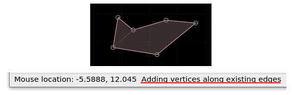
While in this mode, when moving the mouse near existing edges you will see another hollow dot
appear on the edge. Clicking the left mouse button will insert a new vertex at that location.
Hit the Escape key to exit this control mode.
Inserting vertices freehand
To add vertices at an arbitrary location, you first need to have a vertex selected to specify
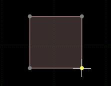
where the new vertices should be inserted. Let's take the example below, where we start with
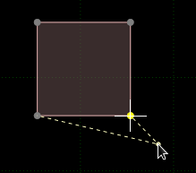
a square shape and we want to add some freehand vertices along the bottom. In this case we should select
one of the vertices at the bottom before starting. Let's say we selected the bottom right vertex...
Hit 'E' twice to enter the freehand insertion control mode. You will see dashed lines connecting
the two vertices on the right. This indicates that any vertices added will go between these two vertices.
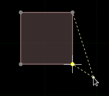
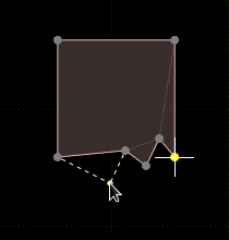
However, that's not what we wanted. Hitting 'E' again changes the direction of insertion:
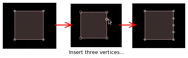
Now we can click with the left mouse button to insert new vertices between the two bottom vertices.
The newly inserted vertices will be inserted next to the originally selected one, so in this case
we should add them heading towards the left. Here is how things will look after inserting three new
vertices.
Hitting 'E' a third time will return to the 'inserting vertices along existing edges' mode, so you
can cycle between these three modes. Hit the Escape key to exit vertex insertion mode.
Note that when multiple vertices are selected you can still use this method, but only one of the
selected vertices is used as the start point for insertion. If more than one vertex is selected
when you start this insertion mode the program will choose one at random to be the start point,
so it's best to make sure you have only one vertex selected before beginning.
Manipulating vertices
Vertex positions can be translated, rotated and scaled in the same way as other items. Here are extra some things to be aware of when manipulating
vertex positions.
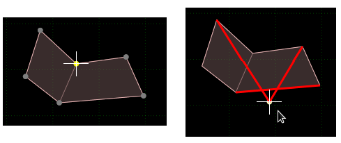
Polygon, loop and line shapes should not have self-intersecting segments. You can tell if the shape has
self-intersecting segments by the red display shown while moving, scaling or rotating them.
For loop and line shapes this just means that the collision detection may not function correctly,
but for polygon shapes it means the polygon cannot be constructed at all.
Using an axis-constrained negative scale to mirror vertices can cause the windings of polygon shapes to be
reversed - you may want to re-adjust the winding to be counter-clockwise after scaling.
Deleting vertices
You can delete vertices by selecting them and pressing the Delete key. Here are some things to
be aware of when deleting vertices.
Deleting vertices of a polygon shape will cause it to become a line shape if there are
less than three remaining vertices.
Deleting vertices of a line or polygon shape will cause it to become a circle shape if there is
only one remaining vertex.
Deleting all vertices of a shape will cause the fixture itself to be deleted.
Action menu options
Since vertices are not standalone items they do not have an 'Add' entry in the action menu.
There are however some useful options in the 'Vertex' submenu. Let's take a look at two of these.
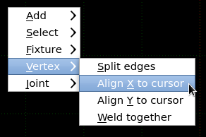
'Split edges' will insert vertices along existing edges, where the edges have both their vertices selected.
For example in the situation below there are two edges which have both of their vertices selected.
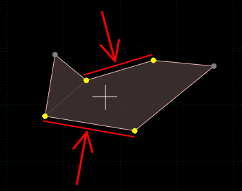
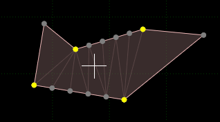
Choosing 'Split edges' will pop up a dialog to enter how many pieces the edge should be split into, and
entering '5' would give this result.
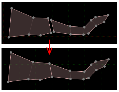
The 'Weld together' option can be handy to place two vertices at exactly the same location. All selected
vertices will be placed at the average of their positions. For example in the situation below, we might want to connect
the two pieces together as seamlessly as possible. This can be done by selecting one vertex from each
side at the top of the join and welding them together, then repeating at the bottom.
Note that the vertices do not get 'welded' in the sense
that they become one vertex - they still exist as separate vertices, just at the same position.