Prismatic joints
See here for a video explaining this topic: YouTube
To edit joints you must first be in joint edit mode (shortcut key 'J').
Prismatic joint creation position
A prismatic joint will be created with the joint anchor position for both bodies placed at the cursor position.
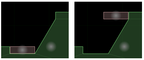
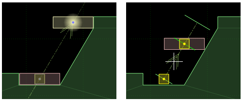
In the image below, suppose we have a slanted elevator which should rise from the start position and
move in the same direction as the slope of the static ground body until it is level with the ground
at the top.
The placement of anchor positions for prismatic joints is usually not as critical as for other joints
(and to adjust the axis direction in the section below it would be easier if the anchors were elsewhere)
but for the sake of clarity lets say the cursor was placed at the center of the dynamic body when
the joint was created.
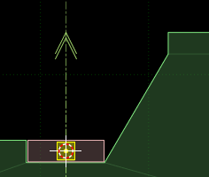
The axis direction is shown by an arrow pointing in the positive direction, and is (0,1) by default
when the joint is created.
Moving joint anchors
Prismatic joint anchor positions can be translated and rotated in a similar way to other items. The main difference
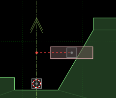
is that one joint has two joint anchors. Initially the manipulation will start with the joint anchor for
bodyA, and you can switch between joint anchors while manipulating them by hitting the same key that started the manipulation.
For example to begin translating joint anchors you would hit 'T', and this would begin translation of the joint
anchor for body A. Hitting 'T' again would switch to translation of the joint anchor for body B.
When the position of the anchor in body B is not on the axis line, a red dashed line will be displayed
to show how far away it is from the axis.
Rotating the joint axis
Hitting 'R' a third time while rotating the joint anchors will allow you to rotate the axis of the joint.
Use the mouse to rotate the axis and click the left mouse button to confirm the new angle, or hit Escape
to cancel the change.
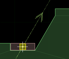
(For this example, aligning the axis would be made easier if the joint anchor had been placed exactly
on the slope itself, but that would make the axis hard to see and these screenshots would be confusing.)
Setting limits
The limit positions for prismatic joints can be set in the properties panel,
but this is often unintuitive. Another way to set the
limits is by moving body B and visually confirming the setting. Hitting the 'L' key will enter
a temporary control mode where body B of the joint will move with the mouse, along the
joint axis.
Initially, when this control mode is entered body B will be shown at the lower limit position.
Hitting 'L' again will switch between setting the lower and upper limit positions.
Move body B with the mouse and click the left button to confirm the new limit position, or hit
Escape to cancel the change.
In the example case we are looking at, the lower limit can be left as the default of zero. Moving
body B to the upper position to set the upper limit for the joint will give the result below. The
limits are shown as thin green lines perpendicular to the axis. The line for the lower limit is a little shorter than
that of the upper limit. The current position of the joint is shown by another green line.
Prismatic joint motors
Joint motor values can be set in the properties panel.
For most applications, the settings for joint motors will be controlled at runtime after loading the scene,
but for motor settings that will not change throughout the lifetime of the scene, or just to experiment
and see how different values behave, it can be handy to try them in R.U.B.E first.